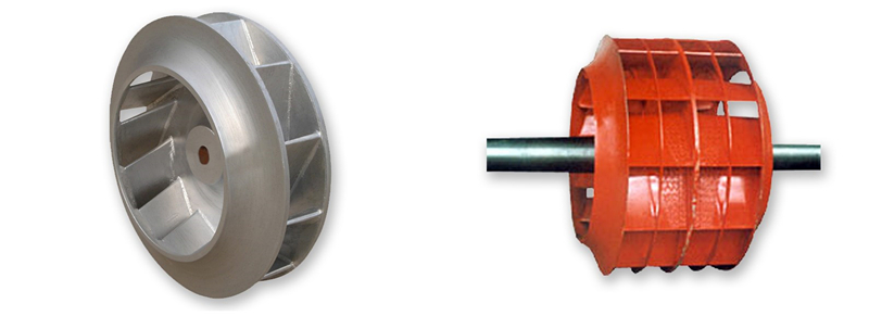
To reduce the axial force borne by the centrifugal pump impeller, it is a common measure to install a sealing ring and balance hole structure on the outer side of the rear cover plate of the centrifugal impeller. Based on the pressure distribution law of rotating fluid, through mathematical analysis calculation, this paper obtains the quantitative calculation method of the leakage amount of the structure, derives the theory of computation formula of the axial force, and proves that the structure can achieve the purpose of reducing the axial force. The research results help to avoid blindness in the design of impeller balance mechanisms and provide reference for correctly determining the relevant geometric dimensions of the impeller.

A high-performance centrifugal pump must not only have good hydraulic performance, but also have the expected service life. In some continuous production lines, such as the chemical and metallurgical industries, customers' requirements for the reliability of key equipment have even become the main indicator for selecting equipment. The stress state of the components of a centrifugal pump is complex, and some components can be subjected to external forces of a very high order of magnitude. This is the main reason for early failure of some components of the pump, such as bearings, seals, and keys, which seriously shortens the maintenance cycle of the pump. Therefore, high-speed rotating impellers must undergo dynamic balance correction.
After the liquid flows through the impeller, the mechanical energy of the fluid increases due to the work done by the impeller, and the main form of this increased energy is pressure energy. The high pressure at the impeller outlet forms an axial distributed force system acting on the outer side of the impeller front and rear cover plates in a certain distribution pattern in the front and rear pump cavities of the pump. Due to the asymmetry of the front and rear cover plate structure, the reverse axial forces on the outside of the front and rear cover plates cannot balance with each other, which results in the axial force acting on the suction direction of the impeller. This axial force can not be ignored especially in high lift low specific speed pumps or large size pumps. There are various hydraulic methods that can reduce the axial force of the impeller. Setting balance holes and sealing rings on the rear cover plate of the impeller is a common method to achieve this goal; However, for a long time, designers' understanding of this effective structure remained more in the qualitative stage, and so far no quantitative analysis of the effect of this structure on reducing axial force has been seen.
During the use of centrifugal impellers, there are many reasons for imbalance, such as wear and scaling of the impeller. Whether it is an impeller treated with thermal spraying or an impeller treated with various methods for descaling, the effect will not be permanent. After long-term use, vibration may still exceed the allowable upper limit. At this point, the imbalance problem of the impeller can only be solved through dynamic balance correction.
295 browse
