
In this article, Huake Zhichuang Dynamic Balancing Machine mainly shares the rotor dynamic balancing technology with everyone, hoping that new and old customers and peers can explore and learn together. Mainly explained from five key aspects: the selection of the front of the calibration, the number of calibration planes, balance speed, vibration measurement points during balance, and the selection of trial balance quality.
1. Selection of school facade
The operation of eliminating the imbalance of the rotor and putting it in a balanced state is called balance correction. Balance correction is carried out on a plane perpendicular to the rotor axis, which is called the correction plane. The method of correcting balance within a calibration plane is called eliminating the imbalance of the rotor and placing it in a balanced state. Balance correction is carried out on a plane perpendicular to the rotor axis, which is called the calibration plane.
For thin disk shaped rotors, the couple imbalance is very small, and in practice, only single sided balancing is performed. For example, flywheels, grinding wheels, fan blades, clutch discs, and rotors with a maximum outer diameter greater than 5 times their net length.
For rotors with a large initial imbalance and excessive vibration during rotation, single sided balancing should be performed before performing dynamic balancing to eliminate static imbalance. It is best to perform the correction in the plane where the center of gravity is located to reduce the imbalance of the couple. If the plane where the center of gravity is located does not allow for weight removal, it should generally be carried out in two planes located on both sides of the plane where the center of gravity is located.
For rigid rotors, there are generally static and even imbalances. Unbalance can be corrected within two randomly selected correction planes perpendicular to the axis, known as biplane balance. The correction method generally adopts the method of weighting or de weighting. The position of the correction plane is generally determined by the structure of the rotor. In order to reduce the time and labor spent in balancing operations, efforts should be made to reduce the amount of correction. Therefore, under possible conditions, the distance and correction radius between the two calibration faces should be increased as much as possible to achieve a good balancing effect.
For rotors such as crankshafts, due to the limitation of the angle position for imbalance correction, using two correction faces cannot meet the balance requirements, so a three-sided or five-sided approach is required. For rotors with actual operating speeds close to or exceeding the critical speed, they are already flexible under operating conditions, so the deflection caused by rotation must be considered during balancing. When the actual working speed is close to the critical speed, more than two multiple speeds can be used to calibrate the front balance; When the rotor speed far exceeds the first critical speed and reaches the second critical speed, a balance method above the four correction planes must be used.
2. Number of correction planes
The selection of the number of correction planes and axial positions is based on the principle of the vibration mode method, including the N method and the N+2 method, which determine the number of correction planes based on the order N of the vibration mode to be balanced. The main principle is to use N+2 planes when balancing low order modes, and N planes when balancing high order modes.
As for the selection of the axial position of the correction plane, the following two points should be considered: it can produce a significant balance effect of the balance weight under the corresponding vibration mode; The possibility and convenience of weighting on a flat surface.
However, in actual balancing, the selected correction plane not only needs to balance the first and second orders, but also needs to balance the third order, which is quite difficult to meet the above two conditions. Therefore, the actual selection of the correction plane is generally as evenly distributed as possible within the effective length of the rotor, which can approximately meet the above two conditions and is also beneficial for reducing high-order imbalance.
For the influence coefficient method, the determination of the number of correction planes and axial positions should be based on the vibration mode method. Otherwise, it may lead to excessive calculated correction quality, which cannot be achieved in practice, or significantly disrupt the balance of higher-order vibration modes.
3. Balancing speed
The goal of balance is to ensure that the vibration of the rotor meets the requirements within a certain speed range. For flexible rotors with a working speed at least greater than the first critical speed, it is not only necessary to ensure that the vibration at the working speed meets the requirements, but also to ensure that they smoothly pass through each critical speed during the start stop process.
4. Vibration measurement points during balance
For the vibration mode method, theoretically speaking, taking a vibration measurement point is sufficient. For the influence coefficient method, the condition for the equation system to have a solution is the number of correction planes. The determination of measurement points includes the selection of axial position and direction of measurement points. The principle for selecting the axial position is: the original vibration is large; It is close to the correction plane and sensitive to the aggravation of that plane.
For other measurement points, they should be discarded as much as possible. On the one hand, in order to reduce the number of measurement points, and on the other hand, because the accuracy of the influence coefficients of these measurement points is poor, substituting them into the equation will significantly reduce the accuracy of the correction quality calculation. In theory, the determination of the direction of the measuring point can be based on the vibration in all three directions of the bearing XYZ for balance calculation. However, there is a good linear relationship with the unbalanced mass, which is vertical vibration, horizontal vibration, and the worst is axial vibration. Moreover, in both horizontal and axial vibrations, there are often large non fundamental components (imbalanced components are fundamental components).
5. Selection of Trial Balance Mass
Regardless of the balance method used, the trial mass must be correctly selected before determining the balance weight. The appropriate selection of the trial balance mass will directly affect the success or failure of the balance test, especially in the balance of measuring amplitude. When the rotor is severely unbalanced or the bearing vibration is too large, if the trial balance mass is too small, it will not cause significant changes in the bearing vibration, and it will not be possible to obtain the correct corrected mass and phase.
The selection of trial weights includes two aspects: size and phase. The selection of phase is generally based on balance experience and reference to balance history. The main principle for selecting test weights is: it is best to add them in the opposite direction of the original imbalance to reduce vibration; The size of the test weight should be appropriate, which should not only cause certain vibration changes, but also cannot cause too large vibration changes.
When the rotor is supported on a balance table for balance experiments, the size of the individual balance test plus balance can be calculated by the following equation:
In the formula, A0 is the original vibration amplitude; K is the sensitivity coefficient of the balance table, m/(g.m).
The sensitivity coefficient K of the balance table is different for rigid first and second order vibrations. For swing and elastic balance tables, the rotor weighs 5-40T, and at the first mode, K1=1.5-2.0 m/(g.m); Under the second-order mode shape, K2=3.0~4.0m/(g.m). The sensitivity coefficient varies depending on the mass of the rotor. Generally, the upper limit is set for rotors with low mass, and the lower limit is set for rotors with high mass.
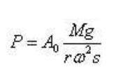
When conducting balance experiments on the rotor on its own support, the mass of each trial addition is estimated by the following equation:
Detailed Analysis of 5 Key Technical Points for Rotor Balancing
In the equation:
P - trial mass on one side of the rotor, kg; A0- Original vibration amplitude of a bearing on one side of the rotor, m; R - installation radius of trial balance mass, m; ω—— The angular velocity of the rotor during balance, rad/s; M - Mass of rotor, kg; G - Gravitational acceleration, m/s ²; S - Sensitivity coefficient, for rotating machinery in power plants, its values can be referred to in the table below.
Reference table for rotor sensitivity coefficient (unit: μ M/rad ²)
1. Selection of school facade
The operation of eliminating the imbalance of the rotor and putting it in a balanced state is called balance correction. Balance correction is carried out on a plane perpendicular to the rotor axis, which is called the correction plane. The method of correcting balance within a calibration plane is called eliminating the imbalance of the rotor and placing it in a balanced state. Balance correction is carried out on a plane perpendicular to the rotor axis, which is called the calibration plane.
For thin disk shaped rotors, the couple imbalance is very small, and in practice, only single sided balancing is performed. For example, flywheels, grinding wheels, fan blades, clutch discs, and rotors with a maximum outer diameter greater than 5 times their net length.
For rotors with a large initial imbalance and excessive vibration during rotation, single sided balancing should be performed before performing dynamic balancing to eliminate static imbalance. It is best to perform the correction in the plane where the center of gravity is located to reduce the imbalance of the couple. If the plane where the center of gravity is located does not allow for weight removal, it should generally be carried out in two planes located on both sides of the plane where the center of gravity is located.
For rigid rotors, there are generally static and even imbalances. Unbalance can be corrected within two randomly selected correction planes perpendicular to the axis, known as biplane balance. The correction method generally adopts the method of weighting or de weighting. The position of the correction plane is generally determined by the structure of the rotor. In order to reduce the time and labor spent in balancing operations, efforts should be made to reduce the amount of correction. Therefore, under possible conditions, the distance and correction radius between the two calibration faces should be increased as much as possible to achieve a good balancing effect.
For rotors such as crankshafts, due to the limitation of the angle position for imbalance correction, using two correction faces cannot meet the balance requirements, so a three-sided or five-sided approach is required. For rotors with actual operating speeds close to or exceeding the critical speed, they are already flexible under operating conditions, so the deflection caused by rotation must be considered during balancing. When the actual working speed is close to the critical speed, more than two multiple speeds can be used to calibrate the front balance; When the rotor speed far exceeds the first critical speed and reaches the second critical speed, a balance method above the four correction planes must be used.
2. Number of correction planes
The selection of the number of correction planes and axial positions is based on the principle of the vibration mode method, including the N method and the N+2 method, which determine the number of correction planes based on the order N of the vibration mode to be balanced. The main principle is to use N+2 planes when balancing low order modes, and N planes when balancing high order modes.
As for the selection of the axial position of the correction plane, the following two points should be considered: it can produce a significant balance effect of the balance weight under the corresponding vibration mode; The possibility and convenience of weighting on a flat surface.
However, in actual balancing, the selected correction plane not only needs to balance the first and second orders, but also needs to balance the third order, which is quite difficult to meet the above two conditions. Therefore, the actual selection of the correction plane is generally as evenly distributed as possible within the effective length of the rotor, which can approximately meet the above two conditions and is also beneficial for reducing high-order imbalance.
For the influence coefficient method, the determination of the number of correction planes and axial positions should be based on the vibration mode method. Otherwise, it may lead to excessive calculated correction quality, which cannot be achieved in practice, or significantly disrupt the balance of higher-order vibration modes.
3. Balancing speed
The goal of balance is to ensure that the vibration of the rotor meets the requirements within a certain speed range. For flexible rotors with a working speed at least greater than the first critical speed, it is not only necessary to ensure that the vibration at the working speed meets the requirements, but also to ensure that they smoothly pass through each critical speed during the start stop process.
4. Vibration measurement points during balance
For the vibration mode method, theoretically speaking, taking a vibration measurement point is sufficient. For the influence coefficient method, the condition for the equation system to have a solution is the number of correction planes. The determination of measurement points includes the selection of axial position and direction of measurement points. The principle for selecting the axial position is: the original vibration is large; It is close to the correction plane and sensitive to the aggravation of that plane.
For other measurement points, they should be discarded as much as possible. On the one hand, in order to reduce the number of measurement points, and on the other hand, because the accuracy of the influence coefficients of these measurement points is poor, substituting them into the equation will significantly reduce the accuracy of the correction quality calculation. In theory, the determination of the direction of the measuring point can be based on the vibration in all three directions of the bearing XYZ for balance calculation. However, there is a good linear relationship with the unbalanced mass, which is vertical vibration, horizontal vibration, and the worst is axial vibration. Moreover, in both horizontal and axial vibrations, there are often large non fundamental components (imbalanced components are fundamental components).
5. Selection of Trial Balance Mass
Regardless of the balance method used, the trial mass must be correctly selected before determining the balance weight. The appropriate selection of the trial balance mass will directly affect the success or failure of the balance test, especially in the balance of measuring amplitude. When the rotor is severely unbalanced or the bearing vibration is too large, if the trial balance mass is too small, it will not cause significant changes in the bearing vibration, and it will not be possible to obtain the correct corrected mass and phase.
The selection of trial weights includes two aspects: size and phase. The selection of phase is generally based on balance experience and reference to balance history. The main principle for selecting test weights is: it is best to add them in the opposite direction of the original imbalance to reduce vibration; The size of the test weight should be appropriate, which should not only cause certain vibration changes, but also cannot cause too large vibration changes.
When the rotor is supported on a balance table for balance experiments, the size of the individual balance test plus balance can be calculated by the following equation:
In the formula, A0 is the original vibration amplitude; K is the sensitivity coefficient of the balance table, m/(g.m).
The sensitivity coefficient K of the balance table is different for rigid first and second order vibrations. For swing and elastic balance tables, the rotor weighs 5-40T, and at the first mode, K1=1.5-2.0 m/(g.m); Under the second-order mode shape, K2=3.0~4.0m/(g.m). The sensitivity coefficient varies depending on the mass of the rotor. Generally, the upper limit is set for rotors with low mass, and the lower limit is set for rotors with high mass.
When conducting balance experiments on the rotor on its own support, the mass of each trial addition is estimated by the following equation:
Detailed Analysis of 5 Key Technical Points for Rotor Balancing
In the equation:
P - trial mass on one side of the rotor, kg; A0- Original vibration amplitude of a bearing on one side of the rotor, m; R - installation radius of trial balance mass, m; ω—— The angular velocity of the rotor during balance, rad/s; M - Mass of rotor, kg; G - Gravitational acceleration, m/s ²; S - Sensitivity coefficient, for rotating machinery in power plants, its values can be referred to in the table below.
Reference table for rotor sensitivity coefficient (unit: μ M/rad ²)
340 browse