
The process of balancing a rotor, also known as a balance test, involves measuring its imbalance and correcting it to reduce its imbalance; It is an important process in rotor machining.
Is everyone familiar with the dynamic balancing process and methods of different rotors in balancing machines? Below, Huake Zhichuang Dynamic Balancing Machine will share our experience and methods of performing dynamic balancing testing on different rotor workpieces.
1、 Rotors with rolling bearings
For rotors with rolling bearings, it is best to balance them together to eliminate the imbalance caused by the eccentricity of the inner ring of the rolling bearing. Rotors with bearings are generally supported on a V-shaped support. If a semi-circular support is used, the support should be matched with the rolling shaft to make the lower part of the pad contact the bearing, with a slight gap on both sides. Otherwise, the outer ring will be clamped, affecting free vibration, and causing measurement angle errors.
2、 Balancing of a rotor without its own journal
Many parts that need to be balanced, such as leather pulleys, flywheels, blower impellers, etc., do not have their own journals, and the balance of these rotors must be installed on the process shaft. By using this assembly method for balancing, due to the radial clearance, radial runout, and other errors in the fit between the process shaft and the parts, inevitable errors may occur during balancing. The imbalance caused by the above errors can be calculated through parameters such as part machining accuracy.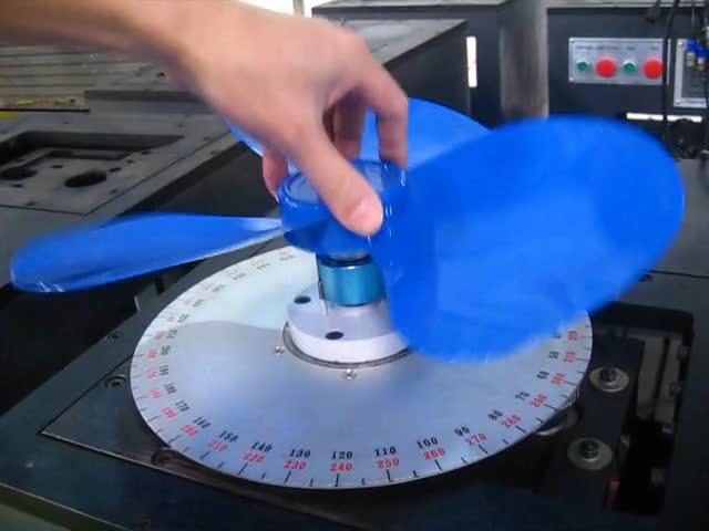
3、 Balance of assembly parts
There is often a situation where the rotor is composed of several parts, such as a high-speed turbocharger rotor, which is composed of two impellers and a shaft. Although it can be balanced as a whole without the impeller being operated separately, for example, when balancing at 1-2 thousand revolutions per minute, it can achieve the specified balance accuracy requirement of 1 micrometer. However, at the actual working speed of 50000 revolutions per minute, due to the imbalance force and force couple of the impeller, Causes the shaft to bend locally and become inoperable. If the impeller is individually balanced at a speed of 1-2 kilorevolutions per minute, assembled, and then balanced to 1 micrometer, the design requirements can be met at the working speed. Therefore, for assembled components, all individual components should be individually balanced according to the specified balance accuracy requirements. The imbalance after assembly is the vector sum of the imbalance of each component.
Due to the arbitrary position of the remaining imbalance of each component, even in the most unfavorable situation, it is only the algebraic sum of the various imbalances. In addition, there may be imbalances caused by fitting during assembly. Therefore, if the balance accuracy requirements of the assembly are high, and only balancing the parts cannot meet the balance accuracy requirements of the assembly, then it is necessary to perform dynamic balance testing on the entire assembly. Balanced assembly parts should generally not be disassembled. If disassembly is required by the process, the corresponding positions of each component should be marked to restore the original corresponding positions during reassembly to ensure the overall balance accuracy.
4、 Rotors with large imbalance
When a rotor with a large amount of imbalance rotates on the balancing machine, it will generate a large centrifugal force, resulting in excessive amplitude of the swing frame causing collision between the swing frame and the support, affecting measurement, and even causing the rotor to fly away from the balancing machine, endangering safety. Therefore, the following measures should be taken for this type of rotor:
1. Static balance should be performed before dynamic balance. If static balancing is carried out on a balancing machine, the balancing machine should use roller bearings. When the rotor is separated from the universal joint, the rotor can rotate freely on that wheel, so that due to the effect of gravity, the heavy side of the rotor will naturally stop below its centerline. At this point, the rotor can be balanced and corrected until it reaches random balance. Static balance correction is best carried out in a balance plane perpendicular to the rotor axis and passing through the center of gravity of the rotor. If this is difficult to achieve, it can be divided into two symmetrical planes on the left and right.
2. First, perform low-speed balancing, reduce the normal balancing speed, and reduce centrifugal force for initial balancing and calibration. When the imbalance is reduced to the allowable range of the normal balancing speed of the balancing machine, then balance the normal speed.
5、 Balancing of rotors with aerodynamic effects
When balancing some rotors with blades, the wind resistance is high, which not only requires the balancing machine to have sufficient driving power, but also the interference of aerodynamic forces may cause instability in the measurement. Therefore, balancing such rotors is often carried out at reduced test speeds, using hard paper shells to block the direction of air flow, or selecting a rotation direction with low wind pressure to reduce driving power and improve measurement stability.
6、 High precision rotor balancing
The balance speed of this type of rotor is generally high. In order to prevent danger caused by excessive centrifugal force, low-speed balance and correction should be carried out first, and then high-speed balance and correction. For medium and large rotors that use universal couplings, the balance of the universal coupling should be checked and corrected first, and then the rotor balance should be carried out. For small rotors, non coupling driving methods should be used, such as belt drive balancing machines or self driving balancing machines, in order to achieve high balancing accuracy.
7、 Balancing of rotors with different experimental and actual working conditions
These types of rotors, such as steam turbines, rotor jet engines, large engines, etc., although well calibrated on balancing machines, can cause new imbalances when assembled and operated under actual working conditions due to expansion caused by heat or deformation caused by electromagnetic forces caused by current. Therefore, on-site balancing and correction are also required for such rotors.
306 browse