
Which type of dynamic balancing machine should be used for brushless motor dynamic balancing?
The development time of brushless motors in China is very short. With the rapid development of science and technology in our country, brushless motors have been applied in many fields, such as household appliances, toys, models, electric vehicles, and so on. Brushless motors are mainly composed of an electric motor and a driver, which belong to electromechanical integrated equipment. Their use can cause various problems, among which the balance problem is the most critical. So, how to choose a dynamic balancing machine for brushless motors? Let's learn more about it based on the knowledge shared by the technical specialist of Huake Zhichuang Dynamic Balancing Machine.
Choosing a brushless motor dynamic balancing machine is one aspect, and choosing a high-quality dynamic balancing machine that suits oneself is also key. When choosing a dynamic balancing machine, we should not just focus on the type of machine, nor blindly listen to others or online comments to choose the type of dynamic balancing machine. We should explore everything ourselves, and the answers we get are the best basis for judging the quality of the type.
The first thing to consider when choosing a brushless motor is whether to use a vertical dynamic balancing machine or a horizontal dynamic balancing machine. In fact, there is no definite answer or explanation for this. Because as long as any type of dynamic balancing machine can achieve high-precision and stable detection, then any type of dynamic balancing machine is acceptable. The purpose of testing is to see if the final result meets the user's requirements. In addition, the accuracy and stability of the dynamic balancing machine detection are also the criteria for judgment. As long as a vertical or horizontal dynamic balancing machine is selected, whichever model can meet this requirement can be chosen.
For high-speed rotors, even with a small eccentricity, it can cause very large centrifugal forces, causing motor vibration, generating noise, accelerating bearing wear, causing high-frequency fatigue damage to rotor components, and reducing the service life of the motor. Therefore, the dynamic balance of the rotor plays a very important role in the manufacturing process of the motor. Technical implementation elements: The purpose of this utility model is to provide a brushless motor rotor dynamic balancing structure that can improve dynamic balance.
To achieve the above objectives, the present utility model adopts the following technical solution: a brushless motor rotor dynamic balancing structure, comprising a magnetic yoke fixed on the rotor shaft, wherein the two ends of the magnetic yoke in the axial direction are respectively fixed with a first dynamic balancing end plate and a second dynamic balancing end plate, and both the first dynamic balancing end plate and the second dynamic balancing end plate are formed with through holes and are sleeved on the rotor shaft through the through holes. One side end surface of the first dynamic balancing end plate facing the second dynamic balancing end plate and one side end surface of the second dynamic balancing end plate facing the first dynamic balancing end plate are in contact with the magnetic yoke. The magnetic steel is placed outside the magnetic yoke, and the magnetic steel is restricted to the first dynamic balancing end plate and the second dynamic balancing end plate. There are several weight reduction holes formed on the first and second dynamic balance end plates between the two dynamic balance end plates.
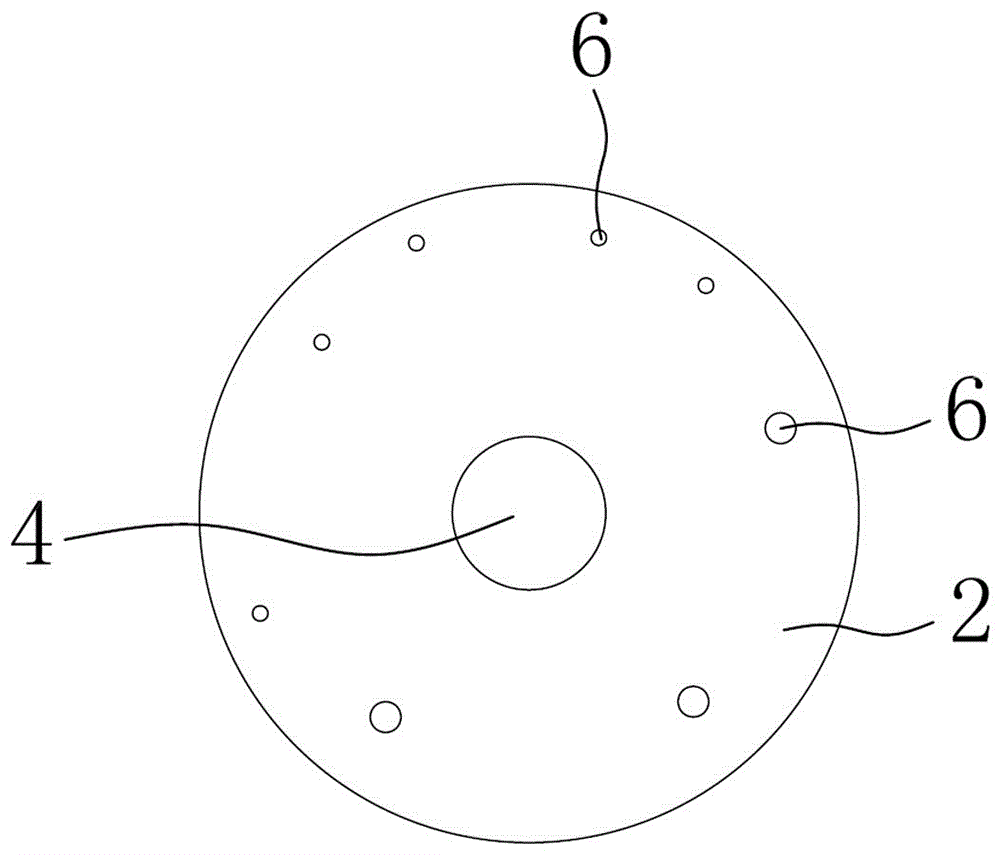
This utility model improves the dynamic balance of the rotor by drilling holes to reduce weight on the first and second dynamic balance end plates. The first and second dynamic balance end plates are used for both weight removal and axial fixation of the magnetic steel to prevent it from falling out. Among them, choose the size and position of the weight reduction hole as needed.
As a preferred option, both the first dynamic balance end plate and the second dynamic balance end plate have an interference fit with the rotor shaft. The above settings are used for fixing the first dynamic balance end plate and the second dynamic balance end plate. The magnetic steel has a tile shaped structure, and several magnetic steels are joined together to form a circular structure. The inner wall of the magnetic steel is in contact with the outer wall of the magnetic yoke.
The first dynamic balance end plate and the second dynamic balance end plate are both arranged in a circular shape, and the outer diameter of the first dynamic balance end plate, the outer diameter of the second dynamic balance end plate, and the outer diameter of the annular magnetic steel are the same. In the above settings, the magnetic steel along the axial direction of the rotor shaft is in contact with the first and second dynamic balance end plates to ensure the limit fixing of the magnetic steel in the axial direction. At the same time, the first and second dynamic balance end plates are lighter in weight to ensure the dynamic balance effect. This utility model has the advantages of improving dynamic balance and fixing magnetic steel.
The development time of brushless motors in China is very short. With the rapid development of science and technology in our country, brushless motors have been applied in many fields, such as household appliances, toys, models, electric vehicles, and so on. Brushless motors are mainly composed of an electric motor and a driver, which belong to electromechanical integrated equipment. Their use can cause various problems, among which the balance problem is the most critical. So, how to choose a dynamic balancing machine for brushless motors? Let's learn more about it based on the knowledge shared by the technical specialist of Huake Zhichuang Dynamic Balancing Machine.
Choosing a brushless motor dynamic balancing machine is one aspect, and choosing a high-quality dynamic balancing machine that suits oneself is also key. When choosing a dynamic balancing machine, we should not just focus on the type of machine, nor blindly listen to others or online comments to choose the type of dynamic balancing machine. We should explore everything ourselves, and the answers we get are the best basis for judging the quality of the type.
The first thing to consider when choosing a brushless motor is whether to use a vertical dynamic balancing machine or a horizontal dynamic balancing machine. In fact, there is no definite answer or explanation for this. Because as long as any type of dynamic balancing machine can achieve high-precision and stable detection, then any type of dynamic balancing machine is acceptable. The purpose of testing is to see if the final result meets the user's requirements. In addition, the accuracy and stability of the dynamic balancing machine detection are also the criteria for judgment. As long as a vertical or horizontal dynamic balancing machine is selected, whichever model can meet this requirement can be chosen.
For high-speed rotors, even with a small eccentricity, it can cause very large centrifugal forces, causing motor vibration, generating noise, accelerating bearing wear, causing high-frequency fatigue damage to rotor components, and reducing the service life of the motor. Therefore, the dynamic balance of the rotor plays a very important role in the manufacturing process of the motor. Technical implementation elements: The purpose of this utility model is to provide a brushless motor rotor dynamic balancing structure that can improve dynamic balance.
To achieve the above objectives, the present utility model adopts the following technical solution: a brushless motor rotor dynamic balancing structure, comprising a magnetic yoke fixed on the rotor shaft, wherein the two ends of the magnetic yoke in the axial direction are respectively fixed with a first dynamic balancing end plate and a second dynamic balancing end plate, and both the first dynamic balancing end plate and the second dynamic balancing end plate are formed with through holes and are sleeved on the rotor shaft through the through holes. One side end surface of the first dynamic balancing end plate facing the second dynamic balancing end plate and one side end surface of the second dynamic balancing end plate facing the first dynamic balancing end plate are in contact with the magnetic yoke. The magnetic steel is placed outside the magnetic yoke, and the magnetic steel is restricted to the first dynamic balancing end plate and the second dynamic balancing end plate. There are several weight reduction holes formed on the first and second dynamic balance end plates between the two dynamic balance end plates.
This utility model improves the dynamic balance of the rotor by drilling holes to reduce weight on the first and second dynamic balance end plates. The first and second dynamic balance end plates are used for both weight removal and axial fixation of the magnetic steel to prevent it from falling out. Among them, choose the size and position of the weight reduction hole as needed.
As a preferred option, both the first dynamic balance end plate and the second dynamic balance end plate have an interference fit with the rotor shaft. The above settings are used for fixing the first dynamic balance end plate and the second dynamic balance end plate. The magnetic steel has a tile shaped structure, and several magnetic steels are joined together to form a circular structure. The inner wall of the magnetic steel is in contact with the outer wall of the magnetic yoke.
The first dynamic balance end plate and the second dynamic balance end plate are both arranged in a circular shape, and the outer diameter of the first dynamic balance end plate, the outer diameter of the second dynamic balance end plate, and the outer diameter of the annular magnetic steel are the same. In the above settings, the magnetic steel along the axial direction of the rotor shaft is in contact with the first and second dynamic balance end plates to ensure the limit fixing of the magnetic steel in the axial direction. At the same time, the first and second dynamic balance end plates are lighter in weight to ensure the dynamic balance effect. This utility model has the advantages of improving dynamic balance and fixing magnetic steel.
342 browse