
To solve the problem of weight testing at high speed during the dynamic balancing process of flexible spindle rotors in machine tools, a low-speed non weight testing dynamic balancing method for flexible spindle rotors is proposed. On the basis of constructing the dynamic model of machine tool spindle, according to the theory of rigid body mechanics, by extracting the mapping relationship between unbalance and vibration response, it is possible to complete the identification of unbalance without trial weight by collecting vibration data once at working speed.
In order to effectively suppress the unbalanced vibration of the spindle rotor with flexible characteristics in the presence of non real imbalance, the modal vibration behavior of the unbalanced spindle in a flexible state was analyzed, and based on this, an unbalanced correction position transfer method was proposed. Simulation and experimental analysis were conducted on a high-speed flexible electric spindle dynamic balancing platform at 7200r/min. The results showed that based on the vibration data collected at the first critical speed, the equivalent unbalance transferred to the two side counterweight planes could be obtained. After correcting this unbalance, the spindle vibration amplitude at the first critical speed was 74.7, and the vibration reduction before and after the critical speed was also significant, effectively suppressing the high-speed mode unbalance.
The equipment manufacturing industry is developing towards high-speed and high-precision direction, which requires precise digital equipment to support it. Numerical control machine tools are one of the carriers of the highest technological level of digital equipment. As a key component of modern numerical control machine tools, the dynamic characteristics of the spindle system directly constrain the manufacturing accuracy of parts. Due to factors such as assembly process, variable working conditions, and wear, the spindle is usually in an unbalanced state. The spindle speed of the machine tool is relatively high, and the spindle vibration caused by imbalance is particularly obvious, which directly affects the machining quality and even leads to damage to the spindle components. Therefore, measures must be taken to control the unbalanced vibration of the spindle. Research on dynamic balancing methods has been conducted both domestically and internationally to address this issue. Dynamic balancing is a typical inverse problem where the output is known and the input is solved. In engineering, multiple starting and stopping operations are usually carried out to add trial weights, in order to obtain characteristic response parameters such as rotor influence coefficients and sensitivity factors. However, weight testing means an interruption in the automation process, which undermines the principle of efficient machining, and incorrect weight testing can lead to a sharp deterioration of the high-speed spindle operation status. The ability to achieve efficient and smooth operation of the rotor with minimal trial weight is an important indicator for measuring on-site dynamic balancing methods. If the trial weight selection is appropriate, the effect of "trial weight is weight balancing" can be achieved, and the method that can achieve this effect is called the "no trial weight balancing method".
Most non trial weight balancing methods typically require obtaining rotor vibration information multiple times at or near the critical speed, which increases the complexity and risk of dynamic balancing implementation and can easily reduce the service life of the spindle system. To overcome the above problems, this article combines the theory of rigid body mechanics balance and proposes a strategy for identifying the unbalance of the spindle without trial weight by collecting vibration data of the spindle only once below the critical speed. Furthermore, a modal analysis based unbalance correction position transfer method is studied, which effectively suppresses the unbalance vibration of the flexible spindle at low speeds.
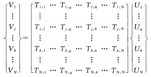
The finite element method for solving unbalance without trial weight has been widely used in rotor dynamics analysis. The finite element model of the main shaft is usually composed of discrete mass disks, continuous mass shaft segments, and elastic bearing seats. By synthesizing the motion differential equations of each element, the motion equation of the main shaft system can be obtained as ioJz,+KZ-n. In Ue (1) equation: z is the system displacement vector; For the angular velocity of rotation; M is the quality matrix; I, For gyro matrix; K is the stiffness matrix; U is an unbalanced vector. For a principal axis system with N nodes, U is {m1 £ leiel, m2e2e2,..., N £ NeiN) T (2), where e is the eccentricity and is the azimuth angle of u at the unit section. Assuming the specific solution of unbalanced response is Z-Ve (3), substitute it into equation (1) to obtain the vibration response vector V-nr-M+t,+K1lU (4). If u is known, V can be solved by equation (4).
Before assembly, the unbalance of the spindle body itself is reduced to a small residual unbalance after offline dynamic balancing on the balancing machine. However, during the operation of the spindle, the imbalance cannot be ignored and is more common in the motor winding and tool holder. This is mainly because the structure of the motor winding is relatively complex, and the phenomenon of centrifugal expansion is more prominent at high speeds, making it difficult to ensure its dynamic balance accuracy. The frequent use and replacement of cutting tools during the machining process, whether it is tool wear or installation eccentricity during tool replacement, can easily lead to new imbalances. Assuming vibration monitoring points are set at the bearing positions at the front and rear ends of the spindle, with corresponding node numbers J and Yes, and node numbers g and h for the tool and motor winding, respectively.
In order to effectively suppress the unbalanced vibration of the spindle rotor with flexible characteristics in the presence of non real imbalance, the modal vibration behavior of the unbalanced spindle in a flexible state was analyzed, and based on this, an unbalanced correction position transfer method was proposed. Simulation and experimental analysis were conducted on a high-speed flexible electric spindle dynamic balancing platform at 7200r/min. The results showed that based on the vibration data collected at the first critical speed, the equivalent unbalance transferred to the two side counterweight planes could be obtained. After correcting this unbalance, the spindle vibration amplitude at the first critical speed was 74.7, and the vibration reduction before and after the critical speed was also significant, effectively suppressing the high-speed mode unbalance.
The equipment manufacturing industry is developing towards high-speed and high-precision direction, which requires precise digital equipment to support it. Numerical control machine tools are one of the carriers of the highest technological level of digital equipment. As a key component of modern numerical control machine tools, the dynamic characteristics of the spindle system directly constrain the manufacturing accuracy of parts. Due to factors such as assembly process, variable working conditions, and wear, the spindle is usually in an unbalanced state. The spindle speed of the machine tool is relatively high, and the spindle vibration caused by imbalance is particularly obvious, which directly affects the machining quality and even leads to damage to the spindle components. Therefore, measures must be taken to control the unbalanced vibration of the spindle. Research on dynamic balancing methods has been conducted both domestically and internationally to address this issue. Dynamic balancing is a typical inverse problem where the output is known and the input is solved. In engineering, multiple starting and stopping operations are usually carried out to add trial weights, in order to obtain characteristic response parameters such as rotor influence coefficients and sensitivity factors. However, weight testing means an interruption in the automation process, which undermines the principle of efficient machining, and incorrect weight testing can lead to a sharp deterioration of the high-speed spindle operation status. The ability to achieve efficient and smooth operation of the rotor with minimal trial weight is an important indicator for measuring on-site dynamic balancing methods. If the trial weight selection is appropriate, the effect of "trial weight is weight balancing" can be achieved, and the method that can achieve this effect is called the "no trial weight balancing method".
Most non trial weight balancing methods typically require obtaining rotor vibration information multiple times at or near the critical speed, which increases the complexity and risk of dynamic balancing implementation and can easily reduce the service life of the spindle system. To overcome the above problems, this article combines the theory of rigid body mechanics balance and proposes a strategy for identifying the unbalance of the spindle without trial weight by collecting vibration data of the spindle only once below the critical speed. Furthermore, a modal analysis based unbalance correction position transfer method is studied, which effectively suppresses the unbalance vibration of the flexible spindle at low speeds.
The finite element method for solving unbalance without trial weight has been widely used in rotor dynamics analysis. The finite element model of the main shaft is usually composed of discrete mass disks, continuous mass shaft segments, and elastic bearing seats. By synthesizing the motion differential equations of each element, the motion equation of the main shaft system can be obtained as ioJz,+KZ-n. In Ue (1) equation: z is the system displacement vector; For the angular velocity of rotation; M is the quality matrix; I, For gyro matrix; K is the stiffness matrix; U is an unbalanced vector. For a principal axis system with N nodes, U is {m1 £ leiel, m2e2e2,..., N £ NeiN) T (2), where e is the eccentricity and is the azimuth angle of u at the unit section. Assuming the specific solution of unbalanced response is Z-Ve (3), substitute it into equation (1) to obtain the vibration response vector V-nr-M+t,+K1lU (4). If u is known, V can be solved by equation (4).
Before assembly, the unbalance of the spindle body itself is reduced to a small residual unbalance after offline dynamic balancing on the balancing machine. However, during the operation of the spindle, the imbalance cannot be ignored and is more common in the motor winding and tool holder. This is mainly because the structure of the motor winding is relatively complex, and the phenomenon of centrifugal expansion is more prominent at high speeds, making it difficult to ensure its dynamic balance accuracy. The frequent use and replacement of cutting tools during the machining process, whether it is tool wear or installation eccentricity during tool replacement, can easily lead to new imbalances. Assuming vibration monitoring points are set at the bearing positions at the front and rear ends of the spindle, with corresponding node numbers J and Yes, and node numbers g and h for the tool and motor winding, respectively.
298 browse