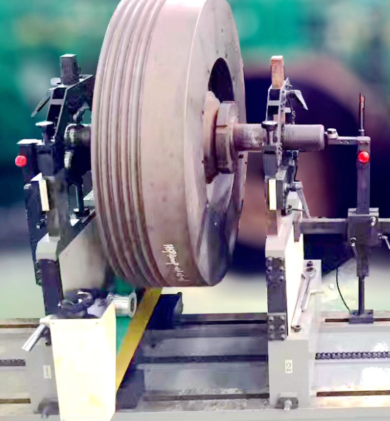
What are the methods for dynamic balancing correction of balancing machine rotors?

When the rotor rotates around its axis, centrifugal force is caused by uneven distribution of mass relative to the axis; This type of unbalanced centrifugal force acting on the rotor bearings can cause vibration, noise, and accelerate bearing wear, seriously endangering the performance and service life of the product. Therefore, a dynamic balancing machine should be used to perform dynamic balancing correction on the rotor.
A dynamic balancing machine is an instrument used to detect the size and location of the unbalance of a rotating workpiece (rotor). So, what are the ways to correct mechanical balance that can be achieved using a dynamic balancing machine? The dynamic balancing machine technician will share the following three methods with everyone.
1. De duplication: In practical applications, it often requires multiple tests and corrections to ensure that the residual imbalance meets the standard. Starting from the process standard of drilling and deduplication, it is usually not the method of drilling one hole, but selecting several locations from the allocated multiple hole positions to drill and deduplication, and achieving the effect of balance correction based on vector synthesis.
2. Weight distribution: For the convenience of weight distribution installation, several evenly distributed screw holes need to be drilled on the balanced rotor first. According to the number of screw holes drilled on the balanced rotor, there are usually three-point weight distribution method and four point weight distribution method. Generally speaking, the location is randomly selected, but our correction work is carried out after the dynamic balance detection work, so we usually choose the location where the phase sensor is located during dynamic balance detection. The counterweight component method is commonly used for single-sided and low-speed dynamic balancing. This method has a high number of starting and stopping times, but does not require phase sensors for detection, resulting in a low detection system cost.
3. Additional dynamic balancing disc: For rotors that require frequent unbalance correction, such as grinding wheel rotors, it is recommended to install a balancing disc on the rotor before balancing. A trapezoidal groove is machined on the balance plate to accommodate additional balance weights.
The size of the balance disk should be designed for different rotor constructions, and the structure of the balance disk should be similar for different rotors. When using the balance plate method to balance the rotor, it is only necessary to understand the starting position of the balance block on the balance plate. After picking up the unbalance, the position of the balance block where the rotor is balanced can be calculated. By moving the balance block to the corresponding position, the rotor can be accurately balanced. This method is easy to operate, has ideal results, and is suitable for widespread promotion.
108 browse
