
The basic control principle of the grinding wheel dynamic balance instrument is to detect and compensate for the vibration imbalance of the grinding wheel. Due to the uneven distribution of abrasive particles in the manufacturing process, the existence of air holes, the uneven surface caused by wear in the grinding process, and the addition of Cutting fluid and other factors, a dynamic imbalance will occur during the high-speed rotation of the wheel, which will seriously affect the precision of the grinder and the precision of the workpiece to be processed.
At present, the design of the grinding wheel dynamic balance instrument is mainly based on the principle of mass compensation. By adding eccentric mass blocks of different masses on the grinding wheel flange, the imbalance generated during rotation is eliminated from the vibration imbalance of the grinding wheel, achieving online automatic balance compensation of the grinding wheel. We usually divide the methods of mass compensation into two types: fluid compensation and rigid body compensation. The balance principle of fluid mass compensation and rigid body mass compensation is fundamentally the same. Rigid body mass compensation adopts a rigid body to eliminate the vibration of the grinding wheel, so the vibration status information of the grinding wheel will not be lost after the grinding machine stops. This method is currently widely used; And fluid quality compensation uses fluid to eliminate the vibration of the grinding wheel, so the vibration state of the grinding wheel will be lost after the grinding machine is stopped, so this method is rarely used.
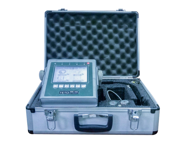
Function/performance description of on-site dynamic balance instrument product:
1. Contains data storage that can be used for program upgrades, data storage, report printing, and language conversion.
2. It has the functions of balancing various rotors before assembly and online balancing and correction after assembly.
3. Suitable for online dynamic balance correction/monitoring/analysis of various rotors in machinery/motors.
4. Using frequency spectrum for rotor vibration analysis to truly present the vibration state.
5. Can perform various rotor single or double sided dynamic balance correction/monitoring/analysis.
6. Can perform vibration unit conversion, vibration allowable value setting/power state presentation.
7. The dynamic balance correction operation can be performed by adding weight or removing weight.
8. Calculation of built-in ISO1940 rotor balance level
9. Add touch LCD.
10. Can be used for hole location allocation/drilling depth calculation.
11. Add rechargeable lithium batteries/strong standby time.
12. Added sensor detection function.
13. New USB Flash Disk/compact mini for easy portability.
14. Add indicator light function.
15. Add an adjustable handle.
16. Add three dynamic balancing functions.
At present, domestic surgical research institutions have achieved a lot of research results, and the dynamic balance instruments developed abroad have been mass-produced and serialized, such as the P7WB grinding wheel dynamic balance electronic system produced by Marposs company in Italy. As a representative of advanced foreign technology, this control system can continuously detect grinding wheel vibration and correct the imbalance of grinding wheels in production. The dynamic balance control device for grinding wheels is widely used in industrialized countries, but its price is relatively expensive for domestic manufacturers and after-sales maintenance is extremely inconvenient. The research on the dynamic balance control device for grinding wheels in our country started relatively late, but in recent years, through cooperative production and technology introduction with developed countries such as Italy, Germany, and Japan, many important theoretical technologies have been formed. The relevant semi-automatic and fully automatic dynamic balance devices have been successfully developed and launched into the market.
The rigid body mass compensation correction method is adopted in the vast majority of dynamic balance control systems. There are two eccentric mass blocks (eccentric gear rings) inside the dynamic balance head, which are driven by the rotation of the DC permanent magnet motor inside to move the eccentric gear rings and adjust the positions of the two eccentric mass blocks. This can obtain different balance forces. The centrifugal force caused by the imbalance of the grinding wheel of the grinding machine will be equal to the combined force vector of the eccentric gear rings, If adjusted properly, the grinding wheel can be in the required dynamic balance state.
Different types of dynamic balancing heads have different balancing abilities and the motion modes of their internal eccentric blocks are also different. However, in summary, they can be divided into polar coordinate mode and component coordinate mode. In polar coordinate mode, two eccentric mass blocks have the same distance from the center of rotation and can rotate in a circle around the center of rotation. Generally, we believe that when two eccentric gear rings rotate in the same direction, the phase of the grinding wheel imbalance can be weakened. When and only when the vibration amplitude of the grinding wheel is at its minimum, the phase balance process ends. At this time, adjust the two eccentric mass blocks to rotate in the opposite direction, Adjust the magnitude of their combined force, and when the vibration amplitude of the grinding wheel of the grinding machine reaches its minimum value again, the amplitude balance process ends. In the component coordinate method, the eccentric mass block moves along two mutually perpendicular straight lines, and we can obtain a composite force of different sizes and directions, keeping the grinding wheel in a dynamic equilibrium state. Usually, adopting polar coordinate design makes it easier to design dynamic balancing heads and study balancing control algorithms.
At present, the design of the grinding wheel dynamic balance instrument is mainly based on the principle of mass compensation. By adding eccentric mass blocks of different masses on the grinding wheel flange, the imbalance generated during rotation is eliminated from the vibration imbalance of the grinding wheel, achieving online automatic balance compensation of the grinding wheel. We usually divide the methods of mass compensation into two types: fluid compensation and rigid body compensation. The balance principle of fluid mass compensation and rigid body mass compensation is fundamentally the same. Rigid body mass compensation adopts a rigid body to eliminate the vibration of the grinding wheel, so the vibration status information of the grinding wheel will not be lost after the grinding machine stops. This method is currently widely used; And fluid quality compensation uses fluid to eliminate the vibration of the grinding wheel, so the vibration state of the grinding wheel will be lost after the grinding machine is stopped, so this method is rarely used.
Function/performance description of on-site dynamic balance instrument product:
1. Contains data storage that can be used for program upgrades, data storage, report printing, and language conversion.
2. It has the functions of balancing various rotors before assembly and online balancing and correction after assembly.
3. Suitable for online dynamic balance correction/monitoring/analysis of various rotors in machinery/motors.
4. Using frequency spectrum for rotor vibration analysis to truly present the vibration state.
5. Can perform various rotor single or double sided dynamic balance correction/monitoring/analysis.
6. Can perform vibration unit conversion, vibration allowable value setting/power state presentation.
7. The dynamic balance correction operation can be performed by adding weight or removing weight.
8. Calculation of built-in ISO1940 rotor balance level
9. Add touch LCD.
10. Can be used for hole location allocation/drilling depth calculation.
11. Add rechargeable lithium batteries/strong standby time.
12. Added sensor detection function.
13. New USB Flash Disk/compact mini for easy portability.
14. Add indicator light function.
15. Add an adjustable handle.
16. Add three dynamic balancing functions.
At present, domestic surgical research institutions have achieved a lot of research results, and the dynamic balance instruments developed abroad have been mass-produced and serialized, such as the P7WB grinding wheel dynamic balance electronic system produced by Marposs company in Italy. As a representative of advanced foreign technology, this control system can continuously detect grinding wheel vibration and correct the imbalance of grinding wheels in production. The dynamic balance control device for grinding wheels is widely used in industrialized countries, but its price is relatively expensive for domestic manufacturers and after-sales maintenance is extremely inconvenient. The research on the dynamic balance control device for grinding wheels in our country started relatively late, but in recent years, through cooperative production and technology introduction with developed countries such as Italy, Germany, and Japan, many important theoretical technologies have been formed. The relevant semi-automatic and fully automatic dynamic balance devices have been successfully developed and launched into the market.
The rigid body mass compensation correction method is adopted in the vast majority of dynamic balance control systems. There are two eccentric mass blocks (eccentric gear rings) inside the dynamic balance head, which are driven by the rotation of the DC permanent magnet motor inside to move the eccentric gear rings and adjust the positions of the two eccentric mass blocks. This can obtain different balance forces. The centrifugal force caused by the imbalance of the grinding wheel of the grinding machine will be equal to the combined force vector of the eccentric gear rings, If adjusted properly, the grinding wheel can be in the required dynamic balance state.
Different types of dynamic balancing heads have different balancing abilities and the motion modes of their internal eccentric blocks are also different. However, in summary, they can be divided into polar coordinate mode and component coordinate mode. In polar coordinate mode, two eccentric mass blocks have the same distance from the center of rotation and can rotate in a circle around the center of rotation. Generally, we believe that when two eccentric gear rings rotate in the same direction, the phase of the grinding wheel imbalance can be weakened. When and only when the vibration amplitude of the grinding wheel is at its minimum, the phase balance process ends. At this time, adjust the two eccentric mass blocks to rotate in the opposite direction, Adjust the magnitude of their combined force, and when the vibration amplitude of the grinding wheel of the grinding machine reaches its minimum value again, the amplitude balance process ends. In the component coordinate method, the eccentric mass block moves along two mutually perpendicular straight lines, and we can obtain a composite force of different sizes and directions, keeping the grinding wheel in a dynamic equilibrium state. Usually, adopting polar coordinate design makes it easier to design dynamic balancing heads and study balancing control algorithms.
404 browse