
What are the hazards of rotor unbalance in the popularization of dynamic balancing machine factories?
What are the hazards of rotor imbalance? We assume that a rotor carries an unbalance, and the centrifugal force it brings is F=me ω 2. Due to the fact that some rotors work at a speed of 10000 revolutions per minute on site, and some large fan rotors also reach 1000 revolutions per minute. The radius is R and the centrifugal force is e. We can see how great the centrifugal force of a rotor with an unbalance of 100 grams is (some rotors have an unbalance of several kilograms or even more), which causes the rotor to vibrate, affecting the performance of the equipment and adding dynamic loads to machine components, thereby shortening their service life; Vibration often produces loud noise and pollutes the environment; If the vibration reaches a certain level, the consequences will be more severe.
Main parameters and maintenance dimensions of the dynamic balancing machine: L × W × H=4.9 × 2 × 2.5 m; balancing speed start-up time<2 minutes; Speed range: 60-10000rPm; Rotor weight {1 Bearing support<25000Kg; 2. Rolling support<20000 Kg}; 95% reduction in imbalance; Power: 75KW.
Due to the fast rotation speed of the rotor and the relatively heavy weight of the cut, we pour oil between the roller and the shaft every time we rotate the car to ensure sufficient oil supply and smooth oil flow in all parts of the lubrication system. According to the lubrication chart in the manual, select the lubricating oil number and keep the grease clean, maintain the hydraulic system oil level, and clean, complete, and intact pressure gauges. Pay attention to checking for abnormal noise and high oil temperature.
The universal joint should be lubricated every two months. Before moving the frame, the track should be wiped clean and oil should be poured. The balance speed should be slightly higher than the measurement speed each time to achieve the best energy effect for the drive motor. However, the speed should not be too high, otherwise it will cause the rotor components to protrude and deform.
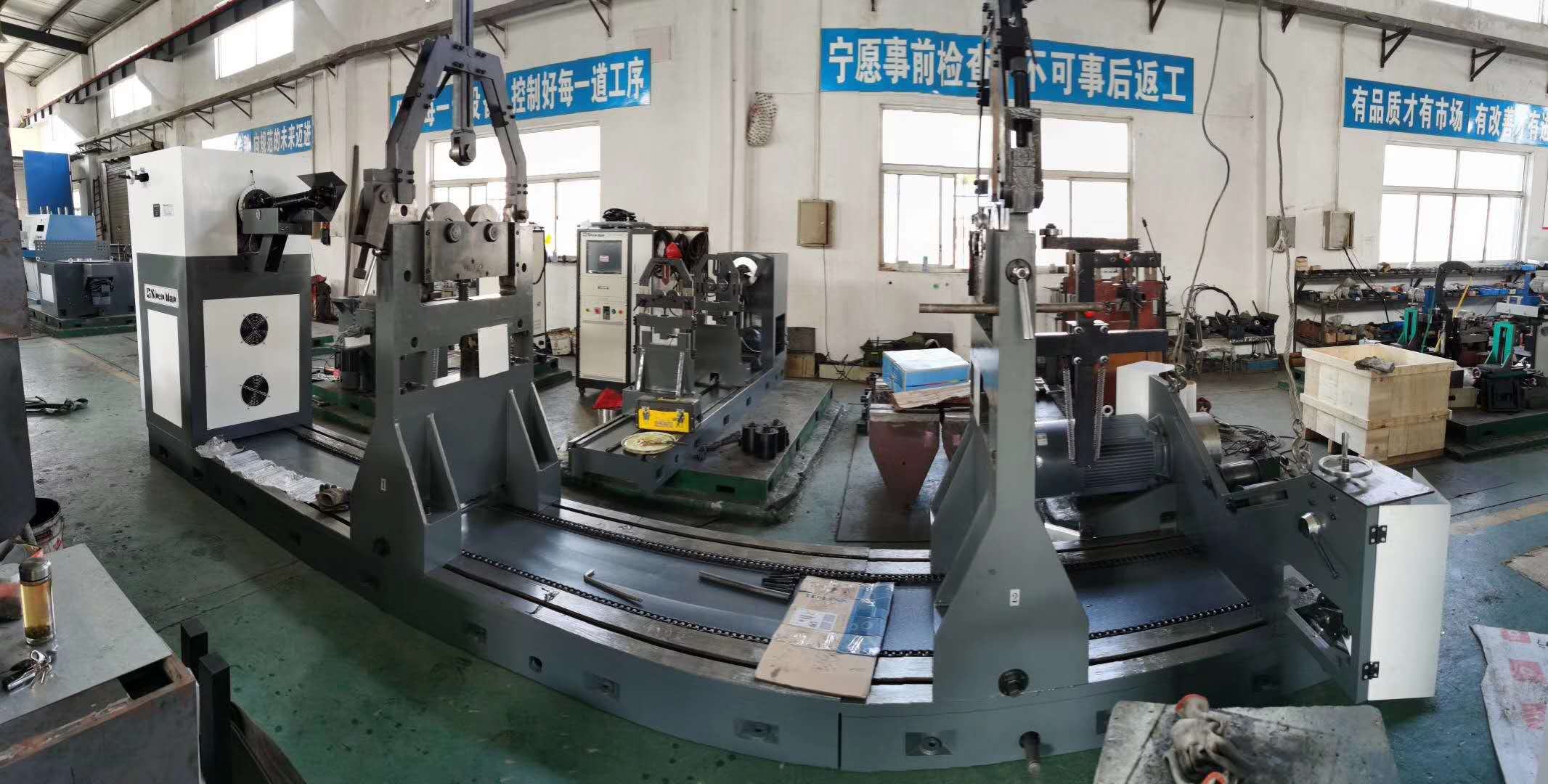
Composition and application of dynamic balancing machine:
The main components of a dynamic balancing machine include a balancing machine track, two adjustable support seats, a spindle box (DC motor, servo motor, spindle, dial and transmission mechanism), and a CNC control box.
The adjustable support seat mainly supports the rotor for balancing, and its main components are two sensors. After the rotor rotates, it becomes unbalanced and causes vibration. After the rotor rotates at a certain speed, the vibration increases due to the increasing centrifugal force. At this time, the sensor starts to work. After the rotor speed stabilizes, the working law of the sensor also begins to stabilize, and the unbalance amount is measured regularly.
After the rotor speed stabilizes during balancing, the sensor transmits the electronic signal to the control box in a regular manner. At this time, the CNC control box changes the electronic signal sent by the sensor into a digital display on the monitor.
In balancing, due to personnel errors (locking errors in each link), errors in the universal joint itself, as well as errors in the rollers, brackets, and connecting flanges, we must remove the unbalance of these errors in order to accurately balance the rotor.
What are the hazards of rotor imbalance? We assume that a rotor carries an unbalance, and the centrifugal force it brings is F=me ω 2. Due to the fact that some rotors work at a speed of 10000 revolutions per minute on site, and some large fan rotors also reach 1000 revolutions per minute. The radius is R and the centrifugal force is e. We can see how great the centrifugal force of a rotor with an unbalance of 100 grams is (some rotors have an unbalance of several kilograms or even more), which causes the rotor to vibrate, affecting the performance of the equipment and adding dynamic loads to machine components, thereby shortening their service life; Vibration often produces loud noise and pollutes the environment; If the vibration reaches a certain level, the consequences will be more severe.
Main parameters and maintenance dimensions of the dynamic balancing machine: L × W × H=4.9 × 2 × 2.5 m; balancing speed start-up time<2 minutes; Speed range: 60-10000rPm; Rotor weight {1 Bearing support<25000Kg; 2. Rolling support<20000 Kg}; 95% reduction in imbalance; Power: 75KW.
Due to the fast rotation speed of the rotor and the relatively heavy weight of the cut, we pour oil between the roller and the shaft every time we rotate the car to ensure sufficient oil supply and smooth oil flow in all parts of the lubrication system. According to the lubrication chart in the manual, select the lubricating oil number and keep the grease clean, maintain the hydraulic system oil level, and clean, complete, and intact pressure gauges. Pay attention to checking for abnormal noise and high oil temperature.
The universal joint should be lubricated every two months. Before moving the frame, the track should be wiped clean and oil should be poured. The balance speed should be slightly higher than the measurement speed each time to achieve the best energy effect for the drive motor. However, the speed should not be too high, otherwise it will cause the rotor components to protrude and deform.
Composition and application of dynamic balancing machine:
The main components of a dynamic balancing machine include a balancing machine track, two adjustable support seats, a spindle box (DC motor, servo motor, spindle, dial and transmission mechanism), and a CNC control box.
The adjustable support seat mainly supports the rotor for balancing, and its main components are two sensors. After the rotor rotates, it becomes unbalanced and causes vibration. After the rotor rotates at a certain speed, the vibration increases due to the increasing centrifugal force. At this time, the sensor starts to work. After the rotor speed stabilizes, the working law of the sensor also begins to stabilize, and the unbalance amount is measured regularly.
After the rotor speed stabilizes during balancing, the sensor transmits the electronic signal to the control box in a regular manner. At this time, the CNC control box changes the electronic signal sent by the sensor into a digital display on the monitor.
In balancing, due to personnel errors (locking errors in each link), errors in the universal joint itself, as well as errors in the rollers, brackets, and connecting flanges, we must remove the unbalance of these errors in order to accurately balance the rotor.
212 browse