
Share the operating steps of the on-site dynamic balancing instrument
Nowadays, rotor dynamic balance detection is very important in the mechanical industry, and people's measurement requirements are becoming increasingly high. The development of machinery has also greatly improved vibration and noise. Due to the high demand for rotor dynamic balance correction that is inconvenient to disassemble, we have improved the quality and reduced the size of the on-site dynamic balance instrument while also achieving more accurate measurement.
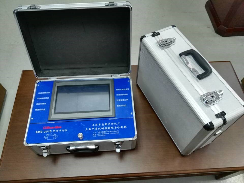
The on-site dynamic balancing instrument is composed of a host, cables, sensors, magnetic seats, speed sensors, and brackets. For different rotating workpieces, select a suitable dynamic balancing machine to measure the corresponding unbalance correction. For beginners, the on-site dynamic balancing instrument with automatic diagnosis and navigation functions is much easier to operate.
On site dynamic balance instrument
What are the precautions and preparation work required before using the on-site dynamic balancing instrument? The master of dynamic balancing technology shares the operation steps of the on-site dynamic balancing instrument.
1、 Preparation work
1. One movable multi hole socket (220V power supply);
2. One electric welding machine;
3. Temporary and formal counterweight blocks (temporary counterweight about 50g, formal counterweight about 500g);
4. One precision electronic balance.
2、 Preparation before testing
1. Install the speed probe on the magnetic seat bracket, attach a reflector at the measuring point of the measured balance rotor, and connect the vibration probe with a cable. Install each probe on the side plane of the front and rear bearing seats (note: the reflector should be firmly attached to the rotor to avoid being thrown out and injuring people).
2. Connect the power cord to the host, speed probe, and vibration probe.
3. Turn on the machine and adjust the position and sensitivity between the speed probe and the balance rotor appropriately. The distance between the speed probe and the reflector is about 5mm, which is the position when the red and green lights are on.
4. After booting up, enter the initial mode and select single-sided balance. Press the mode key MODE, which will display 1PL, and then press the confirm key ENT to confirm. At this time, the Initiat light should be on. If other lights are on, press the CAN key for 3 seconds to reset and then select single-sided balance again.
3、 Initialization operation
1. After turning on, check the lights and indicators on the operation panel (the Initiat light is on).
2. Check if the balancing rotor is in its initial state without temporary counterweights or balancing counterweights.
3. Turn on the motor, drive the rotor to rotate, check the speed indicator (digital display), and when the speed reaches a constant state, press the start button START.
4. During the operation, the actual waveform height and imbalance angle are displayed 5 times in indicator 1 # area. When initialization is complete, the TEST 1 light is on (where the speed is not displayed during the operation and is displayed upon completion).
5. After all operations are completed, stop the machine.
4、 Add temporary counterweight
1. Add a temporary counterweight of known weight at any edge of the stopped impeller, which will be the first point of polar coordinate balance at 0 ° angle and component balance (note: the balance counterweight should be fixed on the same diameter as the counterweight).
2. Start the motor and press the start button START when the impeller reaches a certain speed and stabilizes.
3. After the start, the speed is also not displayed, and the actual waveform height and imbalance angle are displayed 5 times in the indicator. When the operation is completed, the speed is displayed and the TEST 1 light flashes (if the TEST 1 light does not flash, it indicates that the temporary counterweight is too light. In this case, add a larger temporary counterweight and restart the operation).
4. After stopping the balancing rotor, remove the temporary counterweight. The number 1.00 is displayed in the height column of the unbalanced waveform, and "1" flashes. Enter the temporary counterweight value accurately at its position using the setting key and confirm with the ENT key.
5. After entering the temporary weight value, the balance angle and weight of the balance weight are displayed on the operation panel.
5、 Add balance weight
1. According to the rotation direction of the rotor, with 0 ° as the reference, find the position to increase the balance weight based on the balance angle, and weld the balance weight firmly (note: when welding temporary and balance weights to the impeller, the weight of the welding rod used should be considered).
2. After completion, start the motor and measure the vibration value. If it is ideal, complete. If it is not ideal, repeat the operation.
Nowadays, rotor dynamic balance detection is very important in the mechanical industry, and people's measurement requirements are becoming increasingly high. The development of machinery has also greatly improved vibration and noise. Due to the high demand for rotor dynamic balance correction that is inconvenient to disassemble, we have improved the quality and reduced the size of the on-site dynamic balance instrument while also achieving more accurate measurement.
The on-site dynamic balancing instrument is composed of a host, cables, sensors, magnetic seats, speed sensors, and brackets. For different rotating workpieces, select a suitable dynamic balancing machine to measure the corresponding unbalance correction. For beginners, the on-site dynamic balancing instrument with automatic diagnosis and navigation functions is much easier to operate.
On site dynamic balance instrument
What are the precautions and preparation work required before using the on-site dynamic balancing instrument? The master of dynamic balancing technology shares the operation steps of the on-site dynamic balancing instrument.
1、 Preparation work
1. One movable multi hole socket (220V power supply);
2. One electric welding machine;
3. Temporary and formal counterweight blocks (temporary counterweight about 50g, formal counterweight about 500g);
4. One precision electronic balance.
2、 Preparation before testing
1. Install the speed probe on the magnetic seat bracket, attach a reflector at the measuring point of the measured balance rotor, and connect the vibration probe with a cable. Install each probe on the side plane of the front and rear bearing seats (note: the reflector should be firmly attached to the rotor to avoid being thrown out and injuring people).
2. Connect the power cord to the host, speed probe, and vibration probe.
3. Turn on the machine and adjust the position and sensitivity between the speed probe and the balance rotor appropriately. The distance between the speed probe and the reflector is about 5mm, which is the position when the red and green lights are on.
4. After booting up, enter the initial mode and select single-sided balance. Press the mode key MODE, which will display 1PL, and then press the confirm key ENT to confirm. At this time, the Initiat light should be on. If other lights are on, press the CAN key for 3 seconds to reset and then select single-sided balance again.
3、 Initialization operation
1. After turning on, check the lights and indicators on the operation panel (the Initiat light is on).
2. Check if the balancing rotor is in its initial state without temporary counterweights or balancing counterweights.
3. Turn on the motor, drive the rotor to rotate, check the speed indicator (digital display), and when the speed reaches a constant state, press the start button START.
4. During the operation, the actual waveform height and imbalance angle are displayed 5 times in indicator 1 # area. When initialization is complete, the TEST 1 light is on (where the speed is not displayed during the operation and is displayed upon completion).
5. After all operations are completed, stop the machine.
4、 Add temporary counterweight
1. Add a temporary counterweight of known weight at any edge of the stopped impeller, which will be the first point of polar coordinate balance at 0 ° angle and component balance (note: the balance counterweight should be fixed on the same diameter as the counterweight).
2. Start the motor and press the start button START when the impeller reaches a certain speed and stabilizes.
3. After the start, the speed is also not displayed, and the actual waveform height and imbalance angle are displayed 5 times in the indicator. When the operation is completed, the speed is displayed and the TEST 1 light flashes (if the TEST 1 light does not flash, it indicates that the temporary counterweight is too light. In this case, add a larger temporary counterweight and restart the operation).
4. After stopping the balancing rotor, remove the temporary counterweight. The number 1.00 is displayed in the height column of the unbalanced waveform, and "1" flashes. Enter the temporary counterweight value accurately at its position using the setting key and confirm with the ENT key.
5. After entering the temporary weight value, the balance angle and weight of the balance weight are displayed on the operation panel.
5、 Add balance weight
1. According to the rotation direction of the rotor, with 0 ° as the reference, find the position to increase the balance weight based on the balance angle, and weld the balance weight firmly (note: when welding temporary and balance weights to the impeller, the weight of the welding rod used should be considered).
2. After completion, start the motor and measure the vibration value. If it is ideal, complete. If it is not ideal, repeat the operation.
202 browse