
The development of brushless motor in China is very short. With the rapid development of science and technology in China, brushless motor has been applied in many fields, such as household appliances, toys, models, electric vehicles and so on. Brushless motors are mainly composed of two parts: electric motors and drivers, which belong to mechatronics integration equipment. Using them more often can also cause various problems, one of which is the most critical balance problem. So how to choose a dynamic balance machine for brushless motors? Below, based on the knowledge shared by the technical experts of Huake Zhichuang Dynamic Balance Machine, let's have a detailed understanding.
Choosing a dynamic balancing machine for brushless motors is one aspect, and choosing a high-quality dynamic balancing machine that suits oneself is also crucial. When choosing a dynamic balancing machine, we should not only focus on the type of balancing machine, nor blindly follow others or online comments to choose the type of balancing machine. Everything should be explored by ourselves, and the answers we receive are the best basis for judging the quality of the type.
The first thing to consider for brushless motors is whether to use a vertical dynamic balancing machine or a horizontal dynamic balancing machine, but there is actually no exact answer or explanation for this. Because as long as any type of dynamic balancing machine model can achieve high-precision and stable detection, then any type of dynamic balancing machine is acceptable. The purpose of testing is to see if the final result can meet the user's requirements. In addition, the accuracy and stability of the dynamic balancing machine detection are also the criteria for judgment. As long as the vertical or horizontal dynamic balancing machine is selected, whichever model can meet this requirement can be selected.
For high speed rotors, even with a small eccentricity, it can cause significant centrifugal force, causing vibration and noise in the motor, accelerating bearing wear, causing high-frequency fatigue damage to rotor components, and reducing the service life of the motor. Therefore, the dynamic balance of the rotor plays a very important role in the manufacturing process of motors. Technical implementation elements: The purpose of this utility model is to provide a brushless motor rotor dynamic balance structure that can improve dynamic balance.
To achieve the above objectives, this utility model adopts the following technical solution: a brushless motor rotor dynamic balance structure, including a magnetic yoke fixed on the rotor shaft, the two ends of the magnetic yoke axial direction are respectively fixed with a first dynamic balance end plate and a second dynamic balance end plate, and the first dynamic balance end plate and the second dynamic balance end plate are formed with through holes and sleeved on the rotor shaft through the through holes, The end face of the first dynamic balance end plate towards the second dynamic balance end plate and the end face of the second dynamic balance end plate towards the first dynamic balance end plate are both opposed to the magnetic yoke. The magnetic steel is arranged on the outer side of the magnetic yoke, and is limited between the first dynamic balance end plate and the second dynamic balance end plate. The first dynamic balance end plate and the second dynamic balance end plate form several weight reduction holes.
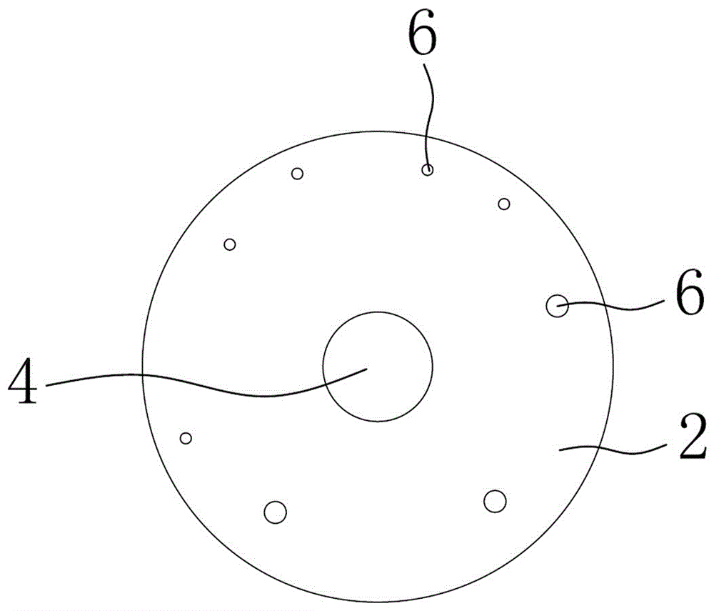
This utility model improves the dynamic balance of the rotor by drilling holes on the first and second dynamic balance end plates to reduce weight. The first and second dynamic balance end plates are not only used for weight removal dynamic balance, but also for fixing the magnetic steel axially to prevent the magnetic steel from falling out. Among them, select the size and position of the weight reduction hole as needed.
As a preferred choice, both the first and second dynamic balance end plates are in an interference fit with the rotor shaft. The above settings are used for fixing the first and second dynamic balance end plates. The magnetic steel is in a tile shaped structure, with several magnetic steel splices forming a circular structure, and the inner wall of the magnetic steel is in contact with the outer wall of the magnetic yoke.
The first and second dynamic balance end plates are both arranged in a circular shape, and the outer diameter of the first dynamic balance end plate, the outer diameter of the second dynamic balance end plate, and the outer diameter of the annular magnetic steel are the same. In the above settings, the parts of the magnetic steel along the axial direction of the rotor shaft are all opposed to the first dynamic balance end plate and the second dynamic balance end plate to ensure the fixed limit of the magnetic steel axial direction. At the same time, the weight of the first dynamic balance end plate and the second dynamic balance end plate is relatively light to ensure the dynamic balance effect. The utility model has the advantages of improving dynamic balance and fixing the magnetic steel.
Choosing a dynamic balancing machine for brushless motors is one aspect, and choosing a high-quality dynamic balancing machine that suits oneself is also crucial. When choosing a dynamic balancing machine, we should not only focus on the type of balancing machine, nor blindly follow others or online comments to choose the type of balancing machine. Everything should be explored by ourselves, and the answers we receive are the best basis for judging the quality of the type.
The first thing to consider for brushless motors is whether to use a vertical dynamic balancing machine or a horizontal dynamic balancing machine, but there is actually no exact answer or explanation for this. Because as long as any type of dynamic balancing machine model can achieve high-precision and stable detection, then any type of dynamic balancing machine is acceptable. The purpose of testing is to see if the final result can meet the user's requirements. In addition, the accuracy and stability of the dynamic balancing machine detection are also the criteria for judgment. As long as the vertical or horizontal dynamic balancing machine is selected, whichever model can meet this requirement can be selected.
For high speed rotors, even with a small eccentricity, it can cause significant centrifugal force, causing vibration and noise in the motor, accelerating bearing wear, causing high-frequency fatigue damage to rotor components, and reducing the service life of the motor. Therefore, the dynamic balance of the rotor plays a very important role in the manufacturing process of motors. Technical implementation elements: The purpose of this utility model is to provide a brushless motor rotor dynamic balance structure that can improve dynamic balance.
To achieve the above objectives, this utility model adopts the following technical solution: a brushless motor rotor dynamic balance structure, including a magnetic yoke fixed on the rotor shaft, the two ends of the magnetic yoke axial direction are respectively fixed with a first dynamic balance end plate and a second dynamic balance end plate, and the first dynamic balance end plate and the second dynamic balance end plate are formed with through holes and sleeved on the rotor shaft through the through holes, The end face of the first dynamic balance end plate towards the second dynamic balance end plate and the end face of the second dynamic balance end plate towards the first dynamic balance end plate are both opposed to the magnetic yoke. The magnetic steel is arranged on the outer side of the magnetic yoke, and is limited between the first dynamic balance end plate and the second dynamic balance end plate. The first dynamic balance end plate and the second dynamic balance end plate form several weight reduction holes.
This utility model improves the dynamic balance of the rotor by drilling holes on the first and second dynamic balance end plates to reduce weight. The first and second dynamic balance end plates are not only used for weight removal dynamic balance, but also for fixing the magnetic steel axially to prevent the magnetic steel from falling out. Among them, select the size and position of the weight reduction hole as needed.
As a preferred choice, both the first and second dynamic balance end plates are in an interference fit with the rotor shaft. The above settings are used for fixing the first and second dynamic balance end plates. The magnetic steel is in a tile shaped structure, with several magnetic steel splices forming a circular structure, and the inner wall of the magnetic steel is in contact with the outer wall of the magnetic yoke.
The first and second dynamic balance end plates are both arranged in a circular shape, and the outer diameter of the first dynamic balance end plate, the outer diameter of the second dynamic balance end plate, and the outer diameter of the annular magnetic steel are the same. In the above settings, the parts of the magnetic steel along the axial direction of the rotor shaft are all opposed to the first dynamic balance end plate and the second dynamic balance end plate to ensure the fixed limit of the magnetic steel axial direction. At the same time, the weight of the first dynamic balance end plate and the second dynamic balance end plate is relatively light to ensure the dynamic balance effect. The utility model has the advantages of improving dynamic balance and fixing the magnetic steel.
324 browse