
To solve the problem of needing to test weight at high speed during the dynamic balancing process of flexible spindle rotors in machine tools, a low speed non test weight dynamic balancing method for flexible spindle rotors is proposed. On the basis of constructing a dynamic model of the machine tool spindle, based on the theory of rigid body mechanics, by extracting the mapping relationship between the imbalance and vibration response, it is possible to complete the identification of the imbalance without trial weight by collecting vibration data once at working speed.
In order to effectively suppress the unbalanced vibration of the main shaft rotor that presents flexible characteristics in non real unbalanced situations, the modal vibration behavior of the unbalanced main shaft under flexible conditions was analyzed, and based on this, a method for correcting the position transfer of the unbalanced amount was proposed. Simulation and experimental analysis were conducted on a high-speed flexible electric spindle dynamic balance platform. The experiment was conducted at 7200r/min, and the results showed that based on the vibration data collected at the first critical speed, the equivalent imbalance transferred to the balance weight planes on both sides can be obtained. After correcting this imbalance, the vibration amplitude of the spindle at the first critical speed was 74.7, and the vibration amplitude before and after the critical speed was also significantly reduced, Effectively suppressed high-speed mode imbalance.
The equipment manufacturing industry is developing towards high speed and precision, which requires precise digital equipment to support. CNC machine tools are one of the carriers of the highest technological level in digital equipment. As a key component of modern CNC machine tools, the spindle system's dynamic characteristics directly affect the manufacturing accuracy of parts. Due to factors such as assembly process, variable operating conditions, and wear, the spindle is usually in an unbalanced state. The spindle speed of the machine tool is relatively high, and the spindle vibration caused by imbalance is particularly obvious, which directly affects the processing quality and even leads to damage to the spindle components. Therefore, measures must be taken to control the unbalanced vibration of the main shaft. In response to this issue, research on dynamic balancing methods has been carried out both domestically and internationally. Dynamic balancing is a typical Inverse problem of solving input with known output. In engineering, multiple starts and stops are usually carried out to add test weights, so as to obtain characteristic response parameters such as rotor influence coefficient and sensitivity factor. However, trial weight implies an interruption in the automation process, which undermines the principle of efficient machining, and incorrect trial weight can cause a sharp deterioration of the high-speed spindle operation status. Whether the efficient and stable operation of the rotor can be achieved through the minimum number of test weights is an important indicator for measuring the on-site dynamic balance method. If the trial weight is selected properly, the effect of "trial weight is counterweight" can be achieved, and the method that can achieve this effect is called "no trial weight balance method".
Most non trial weight balancing methods typically require multiple acquisition of rotor vibration information at or near critical speeds, which increases the complexity and risk of dynamic balancing implementation and can easily reduce the service life of the spindle system. In order to overcome the above problems, based on the rigid body Mechanical equilibrium theory, this paper proposes a strategy to identify the imbalance of the main shaft without test weight by collecting the vibration data of the main shaft only once below the critical speed, and then studies the displacement method of the imbalance correction based on the modal analysis method, which realizes the effective suppression of the imbalance vibration of the flexible main shaft at low speed.
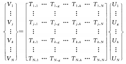
The finite element method for solving unbalance without test weight has been widely used in rotor dynamics analysis. The finite element model of the main shaft is usually composed of discrete mass disc, continuous mass shaft segment, elastic bearing seat and other elements. By synthesizing the differential equations of motion of each element, it can be concluded that the Equations of motion of the main shaft system is one ioJz,+KZ-n. In Ue (1) equation: z is the system displacement vector; Is the self turning speed; M is the Mass matrix; I. Is the gyroscope matrix; K is the Stiffness matrix; U is the unbalanced vector. For a spindle system with N nodes, U {m1 £ leiel, m2e2e2,..., N £ NeiN) T (2) where e is the eccentricity and is the azimuth angle of u at the element cross-section. Let the specific solution of the unbalanced response be Z-Ve (3), which is substituted into equation (1) to obtain the vibration response vector V-nr-M+t,+K1lU (4). If u is known, V can be solved through equation (4).
Before the assembly of the main shaft, the residual imbalance of the shaft itself is very small after offline dynamic balancing on the balancing machine. However, when the spindle is running, the imbalance cannot be ignored, and it mostly occurs at the motor winding and tool handle. This is mainly because the winding structure of the motor is relatively complex, and the phenomenon of centrifugal expansion is more prominent at high speeds. Its dynamic balance accuracy is difficult to ensure, and the frequent use and replacement of tools during the machining process, whether it is tool wear or installation eccentricity during tool replacement, can easily lead to new imbalances. Assuming vibration monitoring points are set at the bearing positions at the front and rear ends of the spindle, with corresponding node numbers J and Y respectively, and node numbers g and h for the tool and motor windings respectively.
In order to effectively suppress the unbalanced vibration of the main shaft rotor that presents flexible characteristics in non real unbalanced situations, the modal vibration behavior of the unbalanced main shaft under flexible conditions was analyzed, and based on this, a method for correcting the position transfer of the unbalanced amount was proposed. Simulation and experimental analysis were conducted on a high-speed flexible electric spindle dynamic balance platform. The experiment was conducted at 7200r/min, and the results showed that based on the vibration data collected at the first critical speed, the equivalent imbalance transferred to the balance weight planes on both sides can be obtained. After correcting this imbalance, the vibration amplitude of the spindle at the first critical speed was 74.7, and the vibration amplitude before and after the critical speed was also significantly reduced, Effectively suppressed high-speed mode imbalance.
The equipment manufacturing industry is developing towards high speed and precision, which requires precise digital equipment to support. CNC machine tools are one of the carriers of the highest technological level in digital equipment. As a key component of modern CNC machine tools, the spindle system's dynamic characteristics directly affect the manufacturing accuracy of parts. Due to factors such as assembly process, variable operating conditions, and wear, the spindle is usually in an unbalanced state. The spindle speed of the machine tool is relatively high, and the spindle vibration caused by imbalance is particularly obvious, which directly affects the processing quality and even leads to damage to the spindle components. Therefore, measures must be taken to control the unbalanced vibration of the main shaft. In response to this issue, research on dynamic balancing methods has been carried out both domestically and internationally. Dynamic balancing is a typical Inverse problem of solving input with known output. In engineering, multiple starts and stops are usually carried out to add test weights, so as to obtain characteristic response parameters such as rotor influence coefficient and sensitivity factor. However, trial weight implies an interruption in the automation process, which undermines the principle of efficient machining, and incorrect trial weight can cause a sharp deterioration of the high-speed spindle operation status. Whether the efficient and stable operation of the rotor can be achieved through the minimum number of test weights is an important indicator for measuring the on-site dynamic balance method. If the trial weight is selected properly, the effect of "trial weight is counterweight" can be achieved, and the method that can achieve this effect is called "no trial weight balance method".
Most non trial weight balancing methods typically require multiple acquisition of rotor vibration information at or near critical speeds, which increases the complexity and risk of dynamic balancing implementation and can easily reduce the service life of the spindle system. In order to overcome the above problems, based on the rigid body Mechanical equilibrium theory, this paper proposes a strategy to identify the imbalance of the main shaft without test weight by collecting the vibration data of the main shaft only once below the critical speed, and then studies the displacement method of the imbalance correction based on the modal analysis method, which realizes the effective suppression of the imbalance vibration of the flexible main shaft at low speed.
The finite element method for solving unbalance without test weight has been widely used in rotor dynamics analysis. The finite element model of the main shaft is usually composed of discrete mass disc, continuous mass shaft segment, elastic bearing seat and other elements. By synthesizing the differential equations of motion of each element, it can be concluded that the Equations of motion of the main shaft system is one ioJz,+KZ-n. In Ue (1) equation: z is the system displacement vector; Is the self turning speed; M is the Mass matrix; I. Is the gyroscope matrix; K is the Stiffness matrix; U is the unbalanced vector. For a spindle system with N nodes, U {m1 £ leiel, m2e2e2,..., N £ NeiN) T (2) where e is the eccentricity and is the azimuth angle of u at the element cross-section. Let the specific solution of the unbalanced response be Z-Ve (3), which is substituted into equation (1) to obtain the vibration response vector V-nr-M+t,+K1lU (4). If u is known, V can be solved through equation (4).
Before the assembly of the main shaft, the residual imbalance of the shaft itself is very small after offline dynamic balancing on the balancing machine. However, when the spindle is running, the imbalance cannot be ignored, and it mostly occurs at the motor winding and tool handle. This is mainly because the winding structure of the motor is relatively complex, and the phenomenon of centrifugal expansion is more prominent at high speeds. Its dynamic balance accuracy is difficult to ensure, and the frequent use and replacement of tools during the machining process, whether it is tool wear or installation eccentricity during tool replacement, can easily lead to new imbalances. Assuming vibration monitoring points are set at the bearing positions at the front and rear ends of the spindle, with corresponding node numbers J and Y respectively, and node numbers g and h for the tool and motor windings respectively.
341 browse